Provent Catch Can Installation
This weekend I finally got around to fitting the Provent 200 Catch Can to our Toyota Landcruiser 200 series V8 Diesel. The kit for the 200 series was supplied to us by Western Filters, in Blacktown NSW. The following is a step by stem DIY instruction showing how you can do it yourself with minimal tools and effort.
First things first….while everyone will tell you this is an easy job, it is not without its frustrations. The space available in the engine bay of the diesel cruiser is quite restricted and getting your hands into the spaces required can be a bit challenging. Also if you drop something in this engine bay, it could fall into one of a hundred confined spaces. You need to pay particular care to deliberately placing items on a surface outside the engine bay.
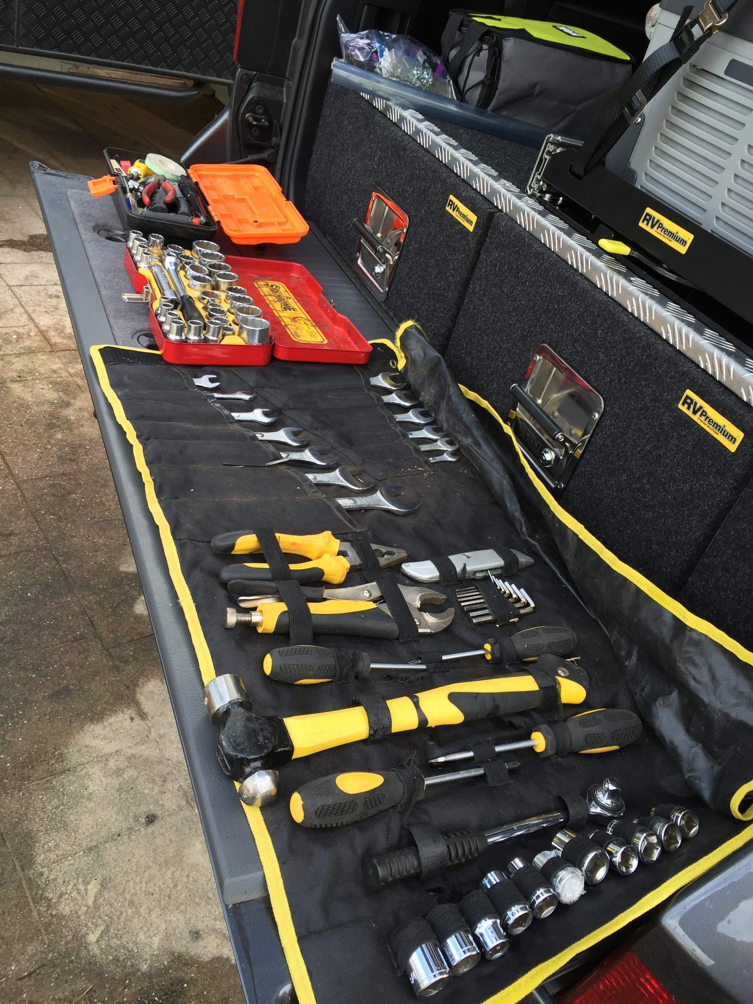
The big advantage is that the kit supplied by Western Filters comes with just about everything you will need to do the job specific to the vehicle your installing into. It takes the guess work out of deciding where to fit the catch can and what length hoses you need. It is a very comprehensive kit.
The instructions that come with the kit are also pretty good however I think for the complete novice, the photos could be a bit clearer. Fortunately I have a little knowledge about most things mechanical so I had little trouble figuring out where everything went.
I did find that the order of the installation process could be modified slightly just to make things a little easier. For instance, I believe you should place the hoses into position before mounting the catch can itself. This helps to establish the orientation of the catch can so that it aligns with the hoses. Makes fitting them much easier.
So to the process:
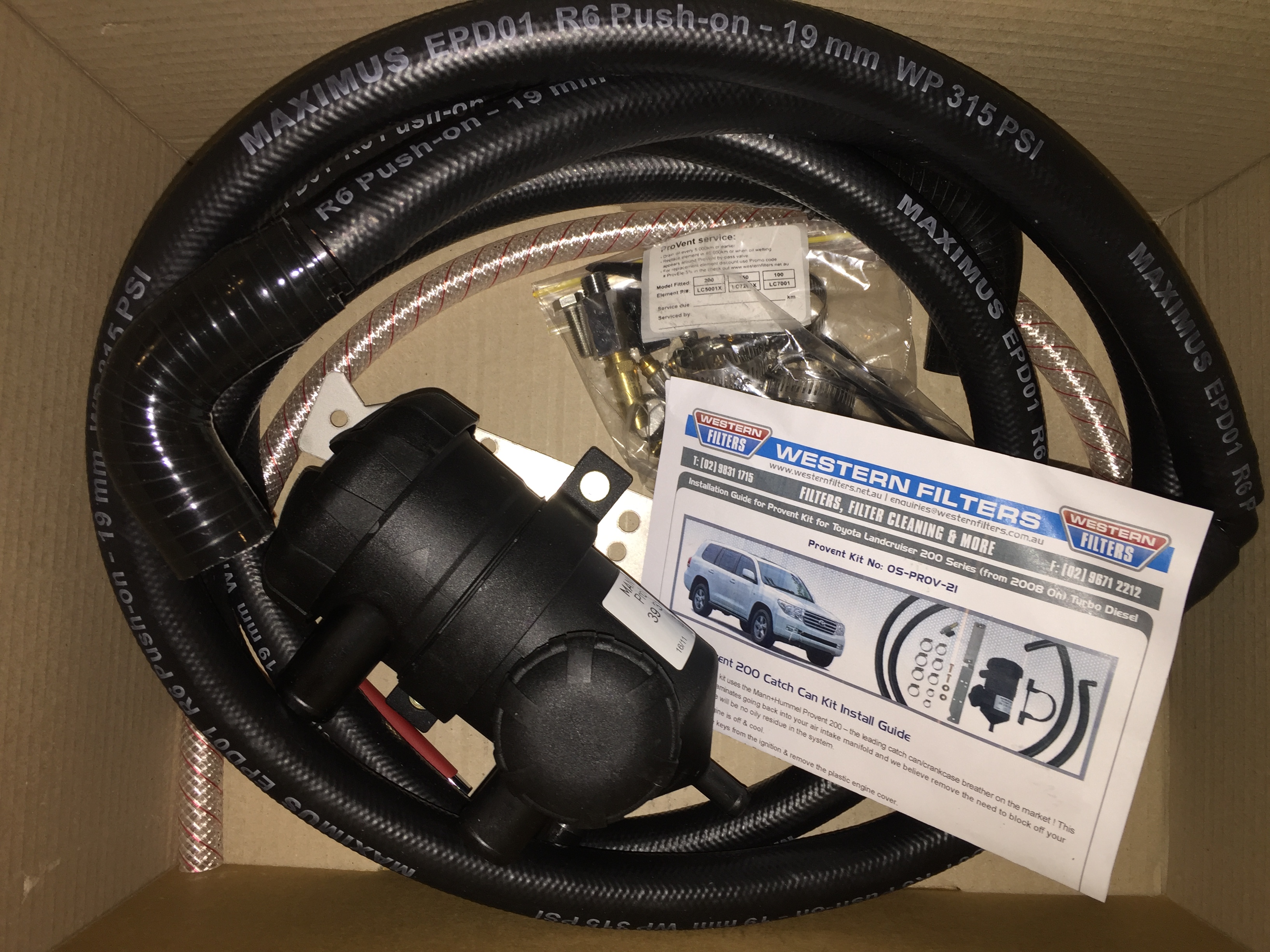
Step 1: Open your box of goodies and examine them to get a good idea of what you have and ensure it matches with the instructions. Most kits would have a similar list so you should have a mounting bracket, the 2 hoses, the catch can itself sitting in a holder that attaches to the mounting bracket. You should also have a drain hose, several hose clamps, some bolts, a drain tap and a few zip ties. I would recommend have a few extra zip ties on hand just to complete the installation.
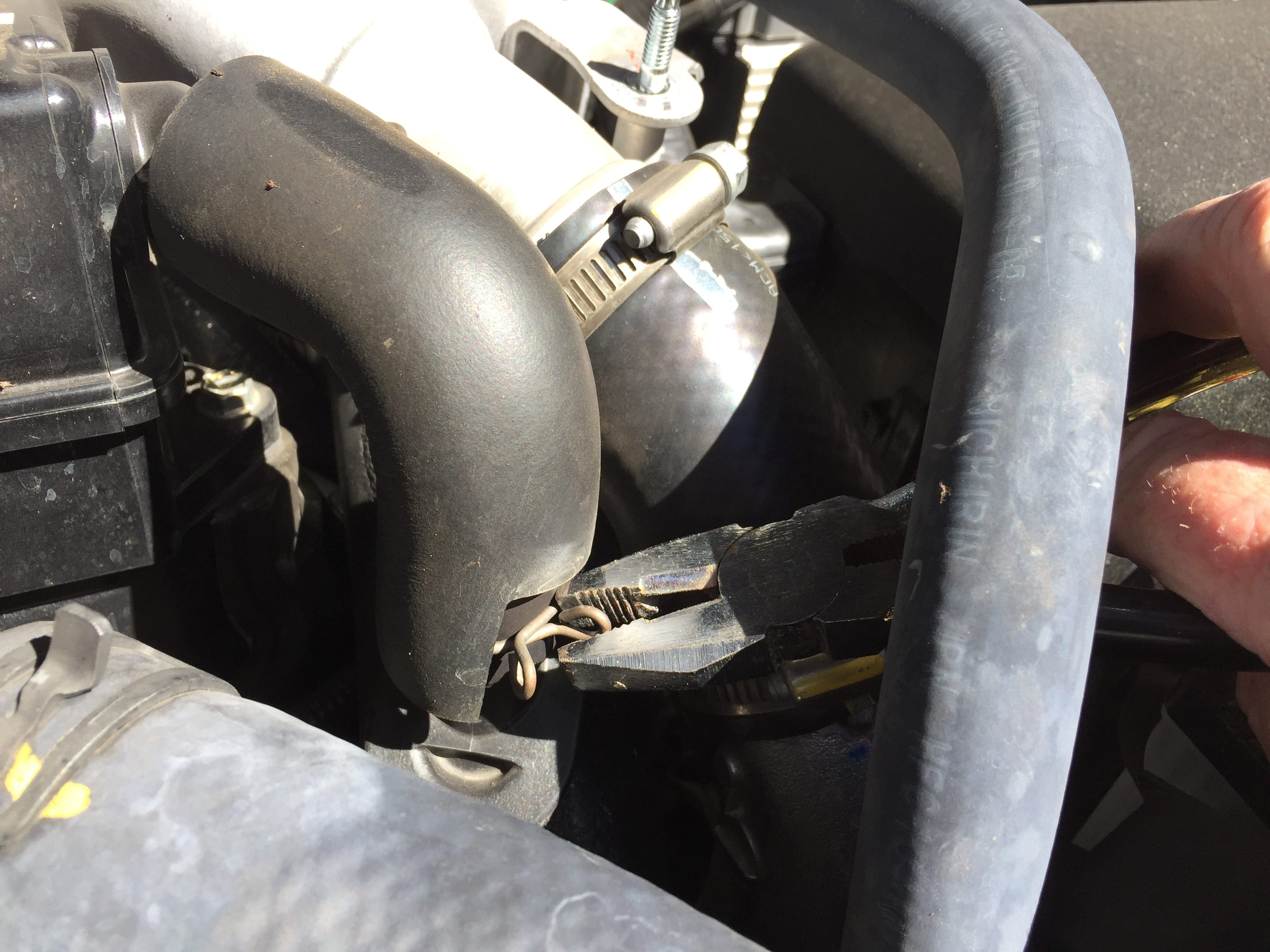
Step 2: Remove the plastic cover from the top of the engine. This is done by simply undoing the 2 nuts holding it down and lifting it forward. Be careful as this is not the strongest piece of plastic in the universe and it may be held down at the back by some double sided tape. Place the cover in a safe place.

Step 3: Disconnect the top connection of the crankcase ventilation hose and swing it around to the 3 o’clock position, keeping the bottom connection in place. It should swivel easily into position.
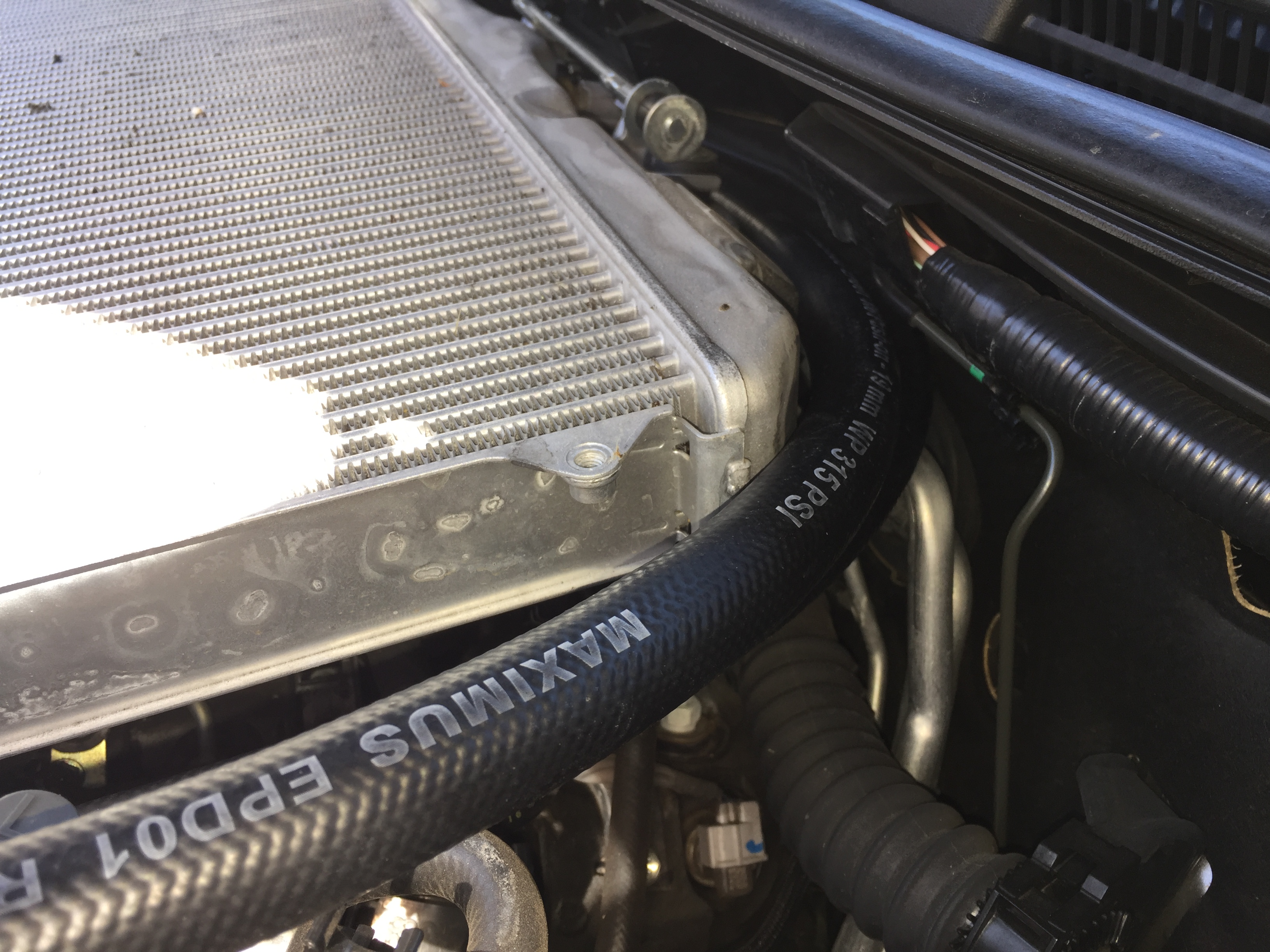
Step 4: Install the 2 hoses. They route around the right hand side and behind the intercooler. Try to push the hoses through the vacant space under the support for the plastic engine cover. This may take some effort as the hoses only just fit through the space. Be careful not to dislodge any sensor connections that also occupy some of this space. They are quite robust so you can use a little force to get the hoses through this space.
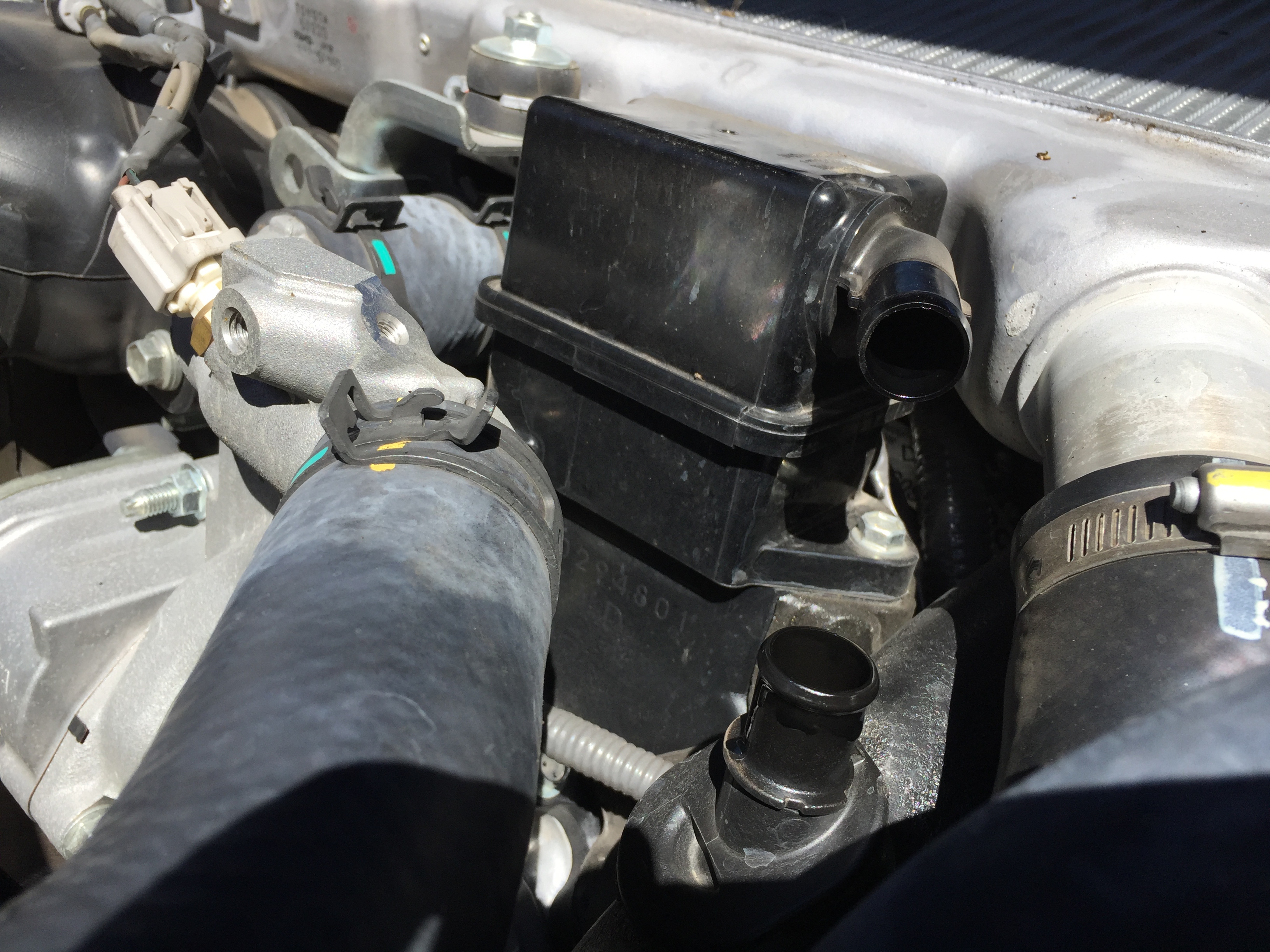
Step 5: Connect the hoses to the crankcase ventilation system taking note of which one is coming from the inter-cooler (top). This is important as this needs to connect to the top connection of the catch can. Remember to slip on the hose clamps before fitting the hoses. Don’t tighten them up just yet. Wait till you have everything in place.
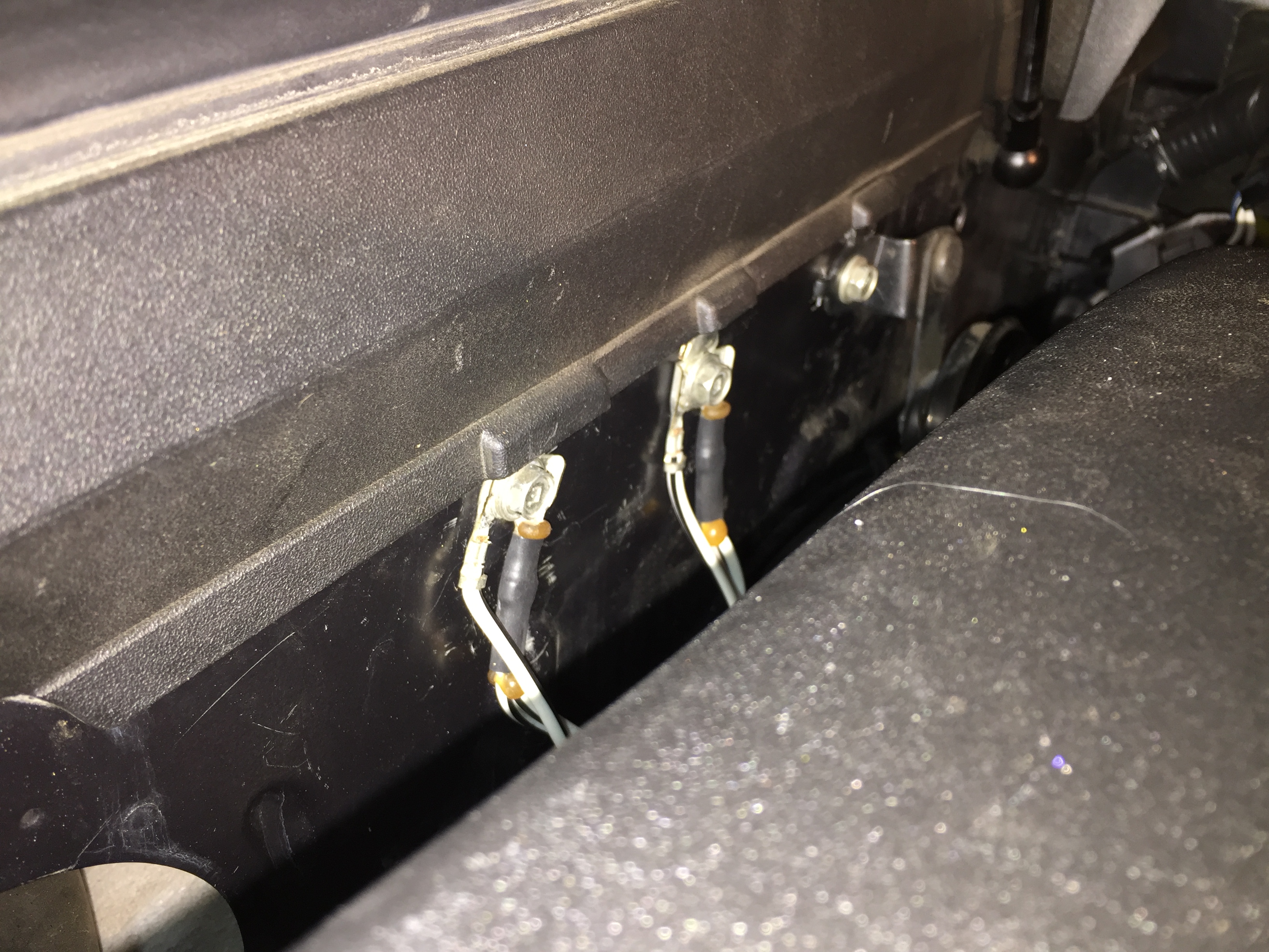
Step 6: Install the mounting bracket in the space indicated in the instructions. I had some issues fitting mine as the holes in the bracket didn’t line up with those in the engine bay. I have no idea why. It was literally a matter of millimetres. Normally I would have just drilled out the hole to make it fit but this bracket is made from some seriously strong stainless steel and I didn’t have a drill bit strong enough to do the job. A quick trip to Bunnings to get one only to find it would have cost me $50 just for one drill bit. I decided to make my own bracket our of gal steel just for the interim. When I find a mate with the necessary equipment, I’ll modify the supplied bracket. Western Filters assured me they sell hundreds of these kits and have never had this issue. I can only surmise that either I’m a complete moron and couldn’t figure out something so simple or, my model cruiser is slightly different to every other.
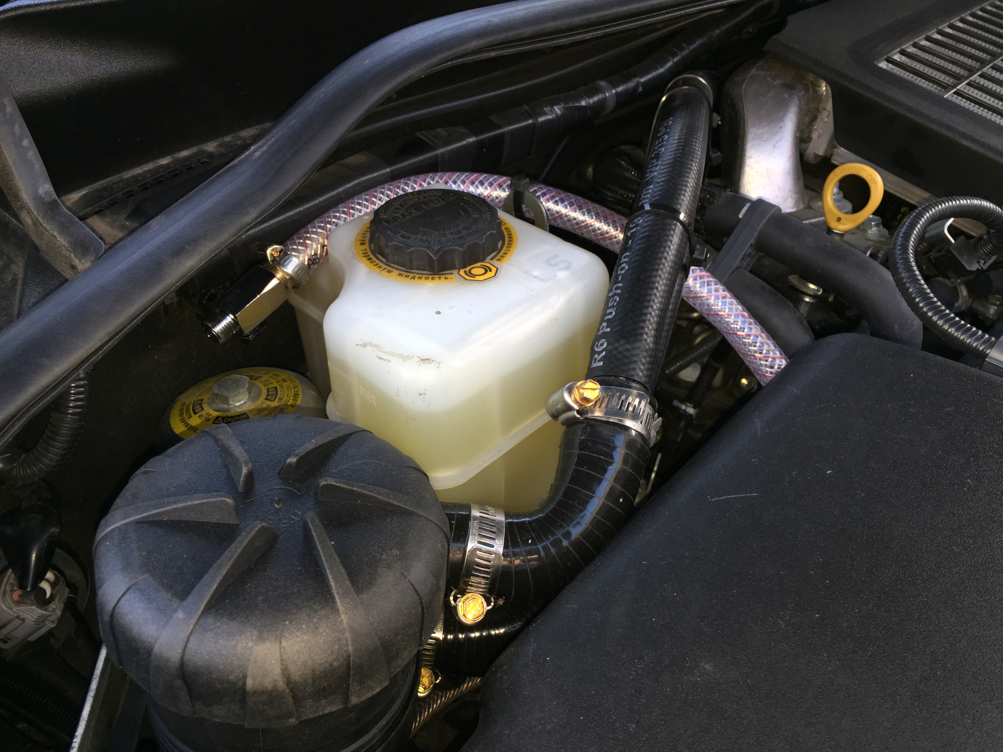
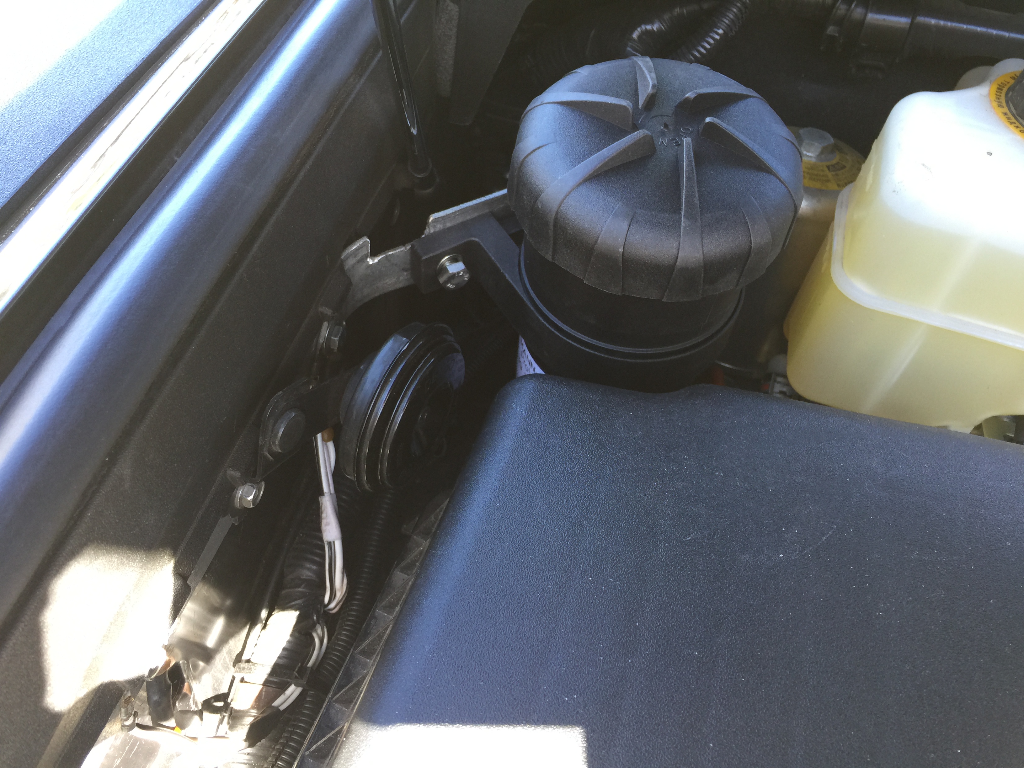
Step 7, with the bracket in place, get your catch can and place it in the spot where it would sit if bolted to the bracket and take note of the hose connections and their orientation relative to the hoses themselves. You may need to rotate the catch can in its holder so the connection and the hoses line up correctly. They are designed to clear other items in the engine bay like the air cleaner box and the brake fluid reservoir. BE VERY CAREFUL. The holder is opened by pulling the plastic rod at the back from the left hand side. It’s quite thin and if forced could easily snap. Use gentle pressure to pull it out from the left to loosen, turn the catch can so that it is correctly orientated and then gently push the rod back into place.
Step 8: Place the hoses onto the catch can remembering to ensure the top hose from the intercooler connects to the top connection on the catch can. Also remember to fit the hose clamps before pushing the hoses on. Do not tighten them up just yet.
Step 9: Attach the tap to the drain hose and connect the other end to the bottom of the catch can. The supplied instructions tell you to remove one of the inner guards and run the drain hose behind it but I wasn’t too happy with this so I left it sitting in the engine bay and can run it down beside the engine when I need to drain it.
Step 10: Place the catch can into its position and bolt it onto the bracket. Some adjustment to the orientation of the catch can in its holder or the position of the hoses may be required. It’s a tight fit and those of you with large hands may find this step a challenge but it will fit.
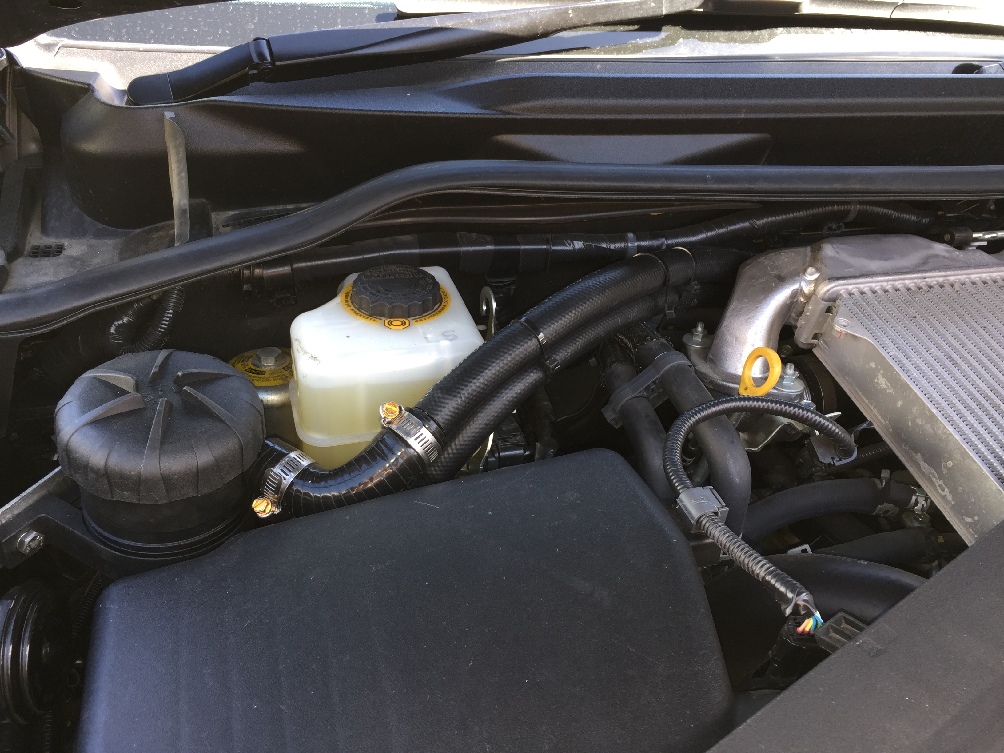
Step 11: With everything in place, recheck the hoses are connected to the correct outlets. If you’re confidant everything is right, tighten all the hose clamps. Use the supplied zip ties to secure the hoses to other existing hoses. I needed a few extra zip ties to ensure the hoses ran clear of rubbing against any other components in the engine bay. Replace the engine cover when you’re finished.
When you first close the bonnet, just be careful to ensure the left hand gas strut clears the mounting bracket. It’s designed to do that but just ensure it does the first time.
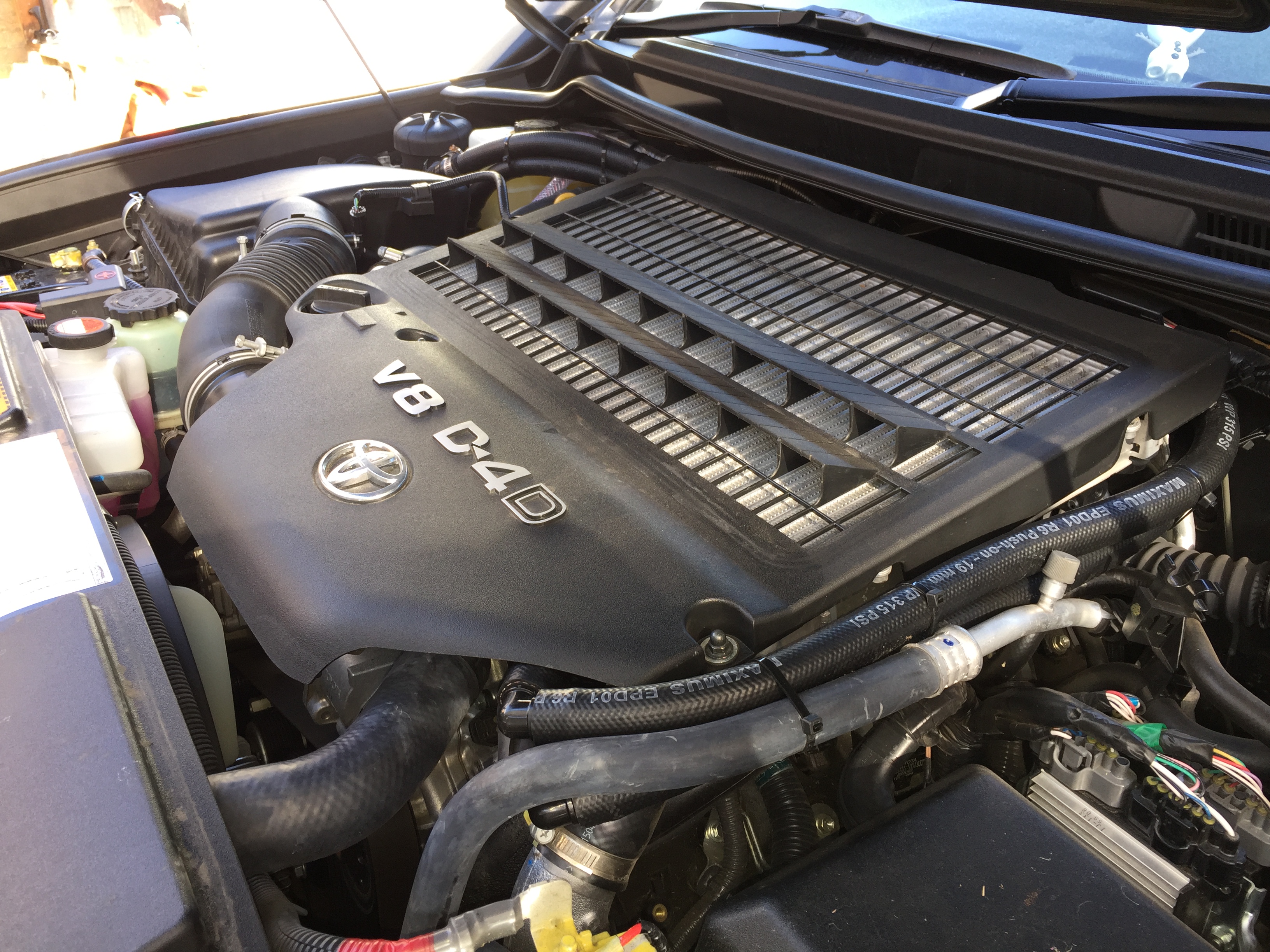
And that’s about it. To test that everything was OK I started the engine and listened for any unusual hissing or sucking sounds. Then, I took it for a test drive at various throttle settings, then returned home and rechecked all the hoses were still secured. There should be no discernible difference in the engine’s performance with the catch can fitted.
We will be monitoring the catch can over the next few months to see how effective it is. For now though, we are quite relieved to finally get this important piece of equipment fitted to the engine of our Crusier.
Thanks go to John from Western Filters for supplying the kit and providing advice when needed.
For more information, visit the Western Filters website.

